CAN Bus DBC File: How Signal Decoding Works in Vehicle Networks
01 September 2026
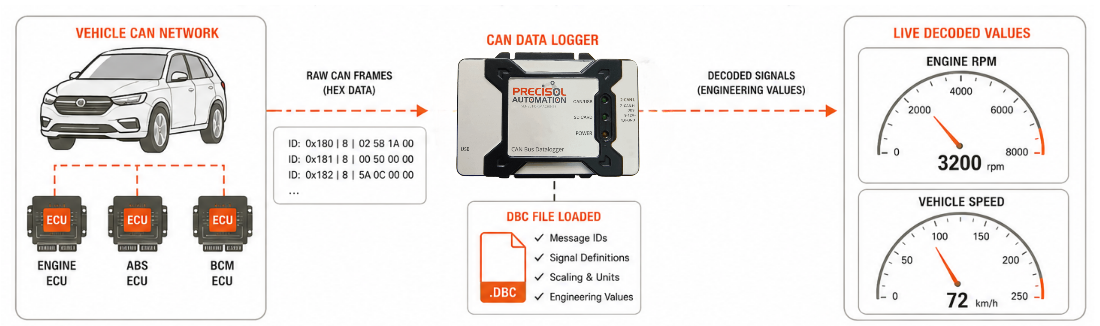
A CAN bus DBC file is the key that unlocks the meaning hidden in raw vehicle CAN bus data — a text-format vehicle network database that maps every CAN message ID and every signal within it to a named, unit-qualified engineering value. Without a CAN bus DBC file, a CAN data logger captures streams of hexadecimal bytes that are meaningless to any engineer who did not design the specific ECU; with a DBC file loaded, those same bytes are automatically decoded by CAN signal decoding software into engine RPM, vehicle speed, coolant temperature, battery voltage, and hundreds of other named parameters — all labelled, scaled, and ready for engineering analysis. The DBC file format — originally developed by Vector Informatik but now universally supported by automotive CAN tools — has become the de facto standard CAN database file format for vehicle network documentation and signal decoding across the automotive and commercial vehicle industries. Understanding how CAN bus DBC files work is fundamental for anyone deploying a CAN data logger, developing a diagnostic tool, or analysing vehicle network data in automotive engineering.
DBC File Format: Structure and Syntax
A CAN bus DBC file is a plain-text file with a defined structure. Understanding the DBC file format helps engineers create, edit, and troubleshoot their vehicle network database files. The core elements of a DBC file:
- NS_ and BS_ Sections: New symbols and bit timing definitions — typically empty header sections in most practical CAN database file applications. These sections define the protocol version and CAN bus timing parameters.
- BU_ (Nodes): Lists all CAN bus nodes (ECUs) in the network — e.g.,
BU_: ECM TCM ABS BCM. Each node name in the CAN bus DBC file corresponds to an ECU that transmits or receives messages on the vehicle network. - BO_ (Messages): The core of the DBC file format. Each message block defines the CAN arbitration ID, message name, data length (DLC), and transmitting node:
BO_ 0x180 EngineData: 8 ECM. All signals within the message are nested under the BO_ block. - SG_ (Signals): Defines each signal's bit position, length, byte order, value type, scale, offset, unit, and receiving nodes:
SG_ EngineRPM : 0|16@1+ (0.25,0) [0|16383.75] "rpm" TCM,BCM. This is where CAN signal decoding parameters are specified — the decoder extracts bits 0–15, multiplies by 0.25, adds 0, and labels the result in rpm.
CAN Signal Decoding: Bit Extraction and Value Calculation
| DBC File Parameter | CAN Signal Decoding Role | Example Value |
|---|---|---|
| Start Bit | Bit position in frame where signal data begins | 0 (first bit of byte 0) |
| Bit Length | Number of bits the signal occupies in the CAN frame | 16 (two bytes for engine RPM) |
| Byte Order | Intel (little-endian) or Motorola (big-endian) bit numbering | @1 = Intel; @0 = Motorola in DBC file format |
| Scale Factor | Multiply raw value by scale to get physical value | 0.25 → raw 12800 = 3200 RPM |
| Offset | Add offset to scaled value | −40 for temperature signals (raw 0 = −40°C) |
| Unit | Physical unit label applied after CAN signal decoding | "rpm", "km/h", "°C", "V" |
Using DBC Files with CAN Data Loggers
Modern CAN bus DBC file support in data loggers enables two modes of operation. In post-processing mode, the logger captures raw CAN frames to storage and the DBC file is applied in analysis software on a PC after the test — the vehicle network database maps each frame ID to its signal definitions, and the software produces decoded CSV or MDF data files. In live decode mode, the CAN bus DBC file is loaded into the logger's firmware before the test; the logger decodes signals in real time and stores only physical values (with timestamps) rather than raw frames. Live decode mode reduces storage requirements and enables the logger to trigger recording or alerts based on decoded signal thresholds — for example, logging a 10-second pre/post buffer when engine coolant temperature exceeds 105°C as defined in the DBC file format.
CAN Bus DBC File Tools with Precisol Automation
Precisol Automation's CAN Data Logger supports CAN bus DBC file loading for both live and post-processing CAN signal decoding — enabling engineers to capture raw CAN frames and decode them using a vehicle network database either onboard or in analysis software. The CAN to USB Adapter interfaces the vehicle CAN bus to a PC running analysis tools with full DBC file format support for real-time signal monitoring and logging.
See CAN signal decoding in practice in our automotive ECU validation case study, or explore how Precisol enables CAN bus analyser applications with comprehensive CAN bus DBC file decode capability.
Frequently Asked Questions
What is a CAN bus DBC file and what does it contain?
A CAN bus DBC file is a vehicle network database in text format defining all CAN messages by their arbitration ID and all signals within each message — including bit position, length, byte order, scale, offset, unit, and valid range. CAN signal decoding tools use the DBC file format to translate raw CAN byte data into named engineering values like engine RPM, temperature, and speed.
How does CAN signal decoding work using a DBC file?
CAN signal decoding using a CAN bus DBC file matches incoming CAN frame IDs to message definitions in the vehicle network database, extracts signal bits using the specified start bit, length, and byte order from the DBC file format, then applies scale and offset to produce physical engineering values. Raw hex bytes become labelled, unit-qualified data — 3200 rpm, 87°C, 65 km/h — that engineers can directly use for analysis.
Where do DBC files come from and are they publicly available?
CAN bus DBC files for proprietary OEM vehicle networks are confidential and distributed within the supply chain under NDA. Publicly available CAN database file options exist for J1939 (standardised heavy vehicle SPNs/PGNs) and OBD-II (standardised service mode PIDs). CAN signal decoding tools for open vehicle network database applications build DBC files from SAE standards documentation or reverse-engineering work.