Automotive Ethernet 100BASE-T1: In-Vehicle Network Architecture and Testing Guide
12 October 2026
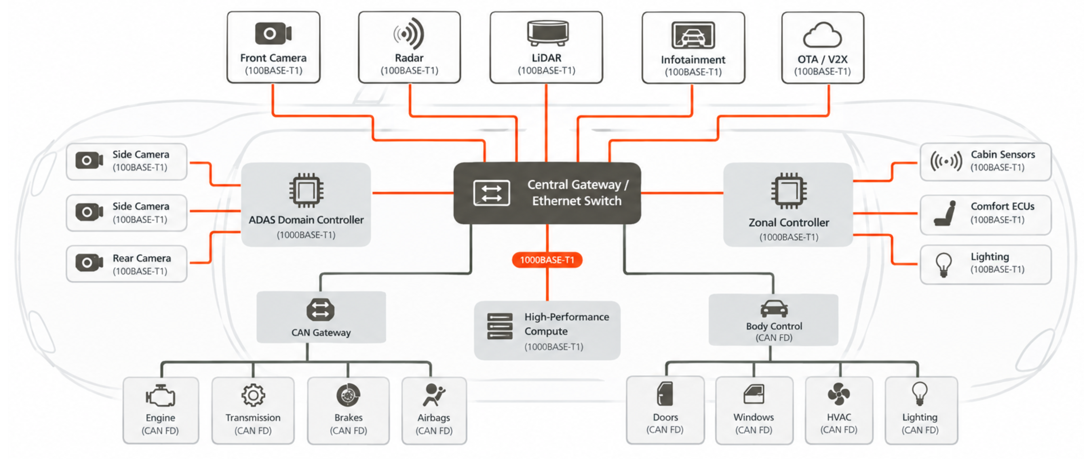
Automotive Ethernet 100BASE-T1 has become the dominant high-bandwidth network technology in modern vehicle architectures — replacing the parallel wiring harnesses that camera, radar, and LiDAR sensor streams would otherwise require, and enabling the centralised computing architectures that underpin advanced driver assistance systems (ADAS) and software-defined vehicles. Defined in IEEE 802.3bw, automotive Ethernet 100BASE-T1 uses a single unshielded twisted pair to carry 100 Mbit/s full-duplex Ethernet between ECUs, domain controllers, and central gateways — at a fraction of the wiring weight and cost of the multi-pair cable that standard 100BASE-TX Ethernet would require in a vehicle. The in-vehicle Ethernet network built on 100BASE-T1 (and its 1 Gbit/s successor 1000BASE-T1) solves the fundamental bandwidth problem of modern automotive electronics: a single front-facing camera generates 150–500 Mbit/s of raw image data; a full ADAS suite with multiple cameras, radar, and LiDAR generates several Gbit/s — data rates that CAN bus cannot approach. Understanding automotive Ethernet vs CAN bus trade-offs, and knowing how to perform automotive Ethernet testing correctly, are now essential competencies for automotive electronics engineers working on any vehicle programme from ADAS to EV powertrain management.
Automotive Ethernet 100BASE-T1: Technical Architecture
- Physical Layer — Single Pair, PAM-3 Signalling: Automotive Ethernet 100BASE-T1 achieves 100 Mbit/s full-duplex over a single unshielded twisted pair using PAM-3 (Pulse Amplitude Modulation with three levels: -1, 0, +1). Simultaneous transmit and receive on the same pair is achieved through echo cancellation at each transceiver. Cable length per segment is up to 15 m — sufficient for in-vehicle trunk routing. The IEEE 802.3bw standard defines the transceiver electrical specifications, cable and connector requirements, and the OPEN Alliance test fixtures used for physical layer automotive Ethernet testing.
- Network Topology — Switched Star via Central Gateway: The in-vehicle Ethernet network in modern vehicles uses a switched star topology centred on a central gateway ECU or domain controller — each ECU, camera, and sensor connects via its own point-to-point automotive Ethernet 100BASE-T1 link to the central switch, which routes frames between ECUs and bridges to CAN bus domains for powertrain and body control. This topology eliminates the collision domains of older bus topologies and provides deterministic, prioritised Ethernet delivery via 802.1Q VLAN tagging and 802.1Qav/Qbv time-sensitive networking (TSN) extensions.
- Automotive Ethernet vs CAN Bus — Where Each Is Used: In modern vehicle electrical architectures, automotive Ethernet vs CAN bus is not an either/or choice — both coexist and are bridged through the central gateway. CAN bus (and CAN FD) handles the safety-critical real-time control domain: engine, transmission, brakes, airbags, and body control ECUs that exchange small messages with hard latency requirements. Automotive Ethernet 100BASE-T1 handles the high-bandwidth domain: ADAS sensor data, infotainment, OTA updates, and V2X Ethernet backhaul. The central gateway ECU translates between CAN frames and Ethernet frames in both directions, maintaining separation while enabling the cross-domain functions that ADAS and autonomous driving require.
- 1000BASE-T1 for Backbone Links: Where 100 Mbit/s is insufficient — camera aggregation links from domain controller to central compute, backbone connections between zonal controllers, and high-resolution map data feeds — vehicles use IEEE 802.3bp 1000BASE-T1 Gigabit Ethernet over the same single twisted pair physical medium. Automotive Ethernet testing for 1000BASE-T1 uses the same OPEN Alliance test infrastructure but with additional PAM-3 eye diagram specifications for the higher symbol rate.
Automotive Ethernet 100BASE-T1 vs CAN Bus: Key Differences
| Parameter | CAN Bus / CAN FD | Automotive Ethernet 100BASE-T1 |
|---|---|---|
| Data Rate | 125 kbit/s – 8 Mbit/s (CAN FD) | 100 Mbit/s (100BASE-T1); 1 Gbit/s (1000BASE-T1) |
| Wiring | 2-wire bus (multi-drop) | Single twisted pair per link (point-to-point) — IEEE 802.3bw |
| Primary Use | Powertrain, chassis, body control — real-time safety messages | In-vehicle Ethernet network for ADAS sensors, OTA, infotainment |
| Automotive Ethernet Testing | CAN protocol analyser, DBC decoding | OPEN Alliance TC2 physical layer, Ethernet frame analyser |
| Latency | Deterministic; worst-case bounded by bit rate and bus load | Low with 802.1Qbv TSN scheduling; varies without TSN |
Automotive Ethernet Testing with Precisol Automation
Precisol Automation's CAN Bus Gateway provides the protocol bridging between CAN bus domains and the in-vehicle Ethernet network — the same gateway function that central ECUs perform in modern vehicles. Testing and validating this bridge with a CAN Data Logger enables engineers to capture and analyse traffic on both sides of the CAN-to-Ethernet boundary, verifying message translation integrity and latency during automotive Ethernet testing of mixed-protocol vehicle networks.
See CAN bus data acquisition in vehicle testing in our autonomous mobile robot testing case study, or explore AMR field testing with CAN bus gateway as an example of mixed-protocol embedded network testing that applies equally to automotive Ethernet 100BASE-T1 integration validation.
Frequently Asked Questions
What is Automotive Ethernet 100BASE-T1 and how does it differ from standard Ethernet?
Automotive Ethernet 100BASE-T1 (IEEE 802.3bw) is a single unshielded twisted pair variant of 100 Mbit/s Ethernet designed for in-vehicle Ethernet networks. Unlike standard 100BASE-TX (which uses two pairs), 100BASE-T1 uses PAM-3 signalling on one pair for full-duplex 100 Mbit/s — halving wiring weight and meeting CISPR 25 automotive EMC requirements. Maximum segment length is 15 m, sufficient for in-vehicle cable runs.
What is the difference between automotive Ethernet vs CAN bus in vehicle networks?
Automotive Ethernet vs CAN bus is a complementary relationship, not a competition. CAN bus (125 kbit/s–8 Mbit/s) handles real-time safety-critical control: engine, brakes, airbags. Automotive Ethernet 100BASE-T1 handles high-bandwidth data: camera streams, ADAS data, OTA updates, infotainment. Modern vehicles use both, bridged through central gateway ECUs. Automotive Ethernet testing validates each layer and the CAN-Ethernet bridge function.
What tests are required for automotive Ethernet 100BASE-T1 validation?
Automotive Ethernet testing covers: IEEE 802.3bw physical layer (PAM-3 eye diagram, insertion/return loss, EMC per CISPR 25); protocol validation (link establishment, frame integrity, VLAN/QoS); and system-level in-vehicle Ethernet network performance (bandwidth, latency, jitter across temperature range). OPEN Alliance TC2 test specifications define the standard test fixture and measurement procedures for automotive Ethernet 100BASE-T1 physical layer compliance.