CAN Bus Error Handling: Understanding Error Frames and Fault Confinement
30 June 2026
One of the most important — and often least understood — aspects of the Controller Area Network standard is its built-in CAN bus error handling system. Unlike many communication protocols that simply drop a corrupted frame and move on, the CAN bus protocol implements a sophisticated multi-layer CAN error detection and CAN bus fault confinement framework. This framework detects errors using five independent mechanisms, communicates errors via a dedicated CAN error frame, and progressively isolates faulty nodes through a state machine that culminates in the bus-off state — all without a central arbiter or network manager.
The Five CAN Error Detection Mechanisms
Robust CAN bus error handling begins with CAN error detection. The CAN bus protocol defines five independent mechanisms for detecting transmission faults — any single mechanism catching a fault is sufficient to trigger a CAN error frame:
- Bit Error: During transmission, every node monitors the bus and compares what it reads to what it transmitted. If the values differ (and the node is not in an arbitration or ACK field), a bit error is detected and CAN bus error handling is triggered immediately.
- Stuff Error: The CAN bus protocol uses bit stuffing — after five consecutive bits of the same polarity, it inserts a bit of the opposite polarity. A CAN error detection stuff error occurs when a sixth consecutive bit of the same polarity is detected, indicating corruption.
- CRC Error: A 15-bit CRC is computed over the data and compared at each receiving node. A mismatch between the transmitted CRC and the computed CRC triggers CAN bus error handling at the receiver, which then transmits a CAN error frame.
- Form Error: Certain fields in the CAN frame — the EOF, IFS, and CRC delimiter — must contain fixed bit values. A form error occurs when these fixed-format fields contain illegal bit patterns, triggering CAN error detection.
- Acknowledgement Error: Every transmitted frame must be acknowledged by at least one other node. If no node drives the ACK slot dominant, the transmitting node detects an acknowledgement error and initiates CAN bus error handling.
The CAN Error Frame
When any node detects one of these faults, it immediately transmits a CAN error frame. The CAN error frame is a special frame type that disrupts the current transmission on purpose — it violates the bit stuffing rule by transmitting 6 consecutive dominant bits. Every other node on the bus detects this CAN error detection violation and also transmits a CAN error frame, creating a cascade that guarantees all nodes know the previous message was invalid and will discard it.
There are two forms of CAN error frame: active and passive. An error-active node transmits an active CAN error frame (6 dominant bits), which is highly disruptive and immediately aborts the current frame. An error-passive node transmits a passive CAN error frame (6 recessive bits), which is less disruptive because dominant bits from other nodes will override it. Which type of CAN error frame a node transmits depends on its current position in the CAN bus fault confinement state machine.
CAN Bus Fault Confinement: The Three-State System
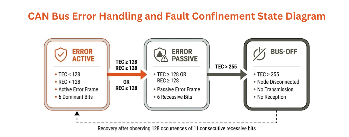
The genius of CAN bus fault confinement lies in its node-level state machine. Each CAN node maintains two internal counters: the Transmit Error Counter (TEC) and the Receive Error Counter (REC). These counters increase when CAN bus error handling detects faults and decrease when transmission and reception succeed. The current counter values determine which of three CAN bus fault confinement states the node is in:
| State | TEC / REC Threshold | CAN Error Frame Type | Network Impact |
|---|---|---|---|
| Error Active | TEC and REC both < 128 | Active (6 dominant bits) | Full participation; errors abort current frame |
| Error Passive | TEC or REC ≥ 128 | Passive (6 recessive bits) | Reduced disruption; must wait longer between retransmissions |
| Bus-Off | TEC > 255 | None — node is disconnected | Node stops all transmissions |
The Bus-Off State and Recovery
The bus-off state is the ultimate sanction in CAN bus fault confinement. When a node's TEC exceeds 255 — meaning it has been transmitting errors repeatedly — the CAN bus error handling system forces that node off the bus entirely. In the bus-off state, the node neither transmits nor receives. To recover from the bus-off state, the node must observe 128 occurrences of 11 consecutive recessive bits on the bus — a process that takes at least 1.28 milliseconds at 1 Mbit/s. This bus-off state recovery delay prevents a malfunctioning node from repeatedly disrupting the network.
Importantly, the bus-off state is a transmit-side concept only. A node with high REC values enters error-passive but never reaches the bus-off state from receive errors alone — this asymmetry prevents a node from being knocked offline simply because it is receiving corrupted frames from a faulty transmitter.
Diagnose CAN Bus Error Handling Issues with Precisol Tools
Diagnosing CAN bus error handling problems — identifying which node is generating CAN error frames, tracking TEC/REC counter progression, or catching intermittent bus-off state events — requires a hardware tool that can capture every frame, including CAN error frames, with microsecond timestamping. Precisol Automation's CAN Bus Gateway provides active network monitoring that can detect and log CAN error frame events in real time. For deep protocol-level CAN error detection analysis, the PreciCAN View CAN Bus Analyser captures raw bus traffic including error and overload frames, giving you full visibility into CAN bus fault confinement behaviour.
See how professional CAN bus error handling analysis accelerates development in our ECU validation case study, or explore how Precisol hardware supports CAN bus network analysis for precise CAN error detection.
Frequently Asked Questions
What triggers a CAN error frame?
A CAN error frame is triggered when any node detects one of five CAN error detection conditions: bit error, stuff error, CRC error, form error, or acknowledgement error. The detecting node immediately transmits a CAN error frame, which signals all other nodes to discard the current message.
What is the difference between error-active and error-passive in CAN bus fault confinement?
In CAN bus fault confinement, error-active nodes transmit active CAN error frames (6 dominant bits) that forcibly abort the current frame. Error-passive nodes transmit passive CAN error frames (6 recessive bits), which are less disruptive. The transition from error-active to error-passive happens when the TEC or REC counter reaches 128.
How does a node recover from the bus-off state?
A node in the bus-off state recovers by observing 128 occurrences of 11 consecutive recessive bits before resuming participation. This CAN bus fault confinement recovery process prevents a faulty node from continuously disrupting CAN bus error handling across the network.