CAN Bus Protocol Explained: Architecture, Messages, and Frame Types
22 June 2026
The CAN bus protocol is a robust, multi-master serial communication standard that allows microcontrollers and electronic devices to communicate with each other without requiring a host computer. Developed by Bosch in 1986 and standardised as ISO 11898, the CAN bus protocol transmits data over a two-wire differential bus, making it exceptionally resistant to electromagnetic interference. Today, the controller area network standard powers everything from passenger car ECUs and heavy commercial vehicles to industrial robots and medical equipment.
Why Was the CAN Bus Protocol Created?
Before the CAN bus protocol existed, automotive wiring was a sprawling tangle of point-to-point connections. Each sensor, actuator, and Electronic Control Unit (ECU) required dedicated wiring to every other component it communicated with. A single vehicle could contain over two kilometres of copper wiring, adding significant weight, cost, and failure risk. Bosch designed the CAN bus protocol in the mid-1980s to replace this wiring complexity with a shared two-wire serial bus where every node could transmit and receive data. This automotive communication protocol reduced wiring dramatically and created the foundation for the sophisticated vehicle electronics we rely on today.
The automotive communication protocol was so effective that it was quickly adopted beyond passenger cars. Today, the controller area network standard is used in agricultural machinery, maritime vessels, industrial automation systems, and medical devices — anywhere reliable, real-time communication between distributed nodes is critical.
CAN Bus Protocol Architecture
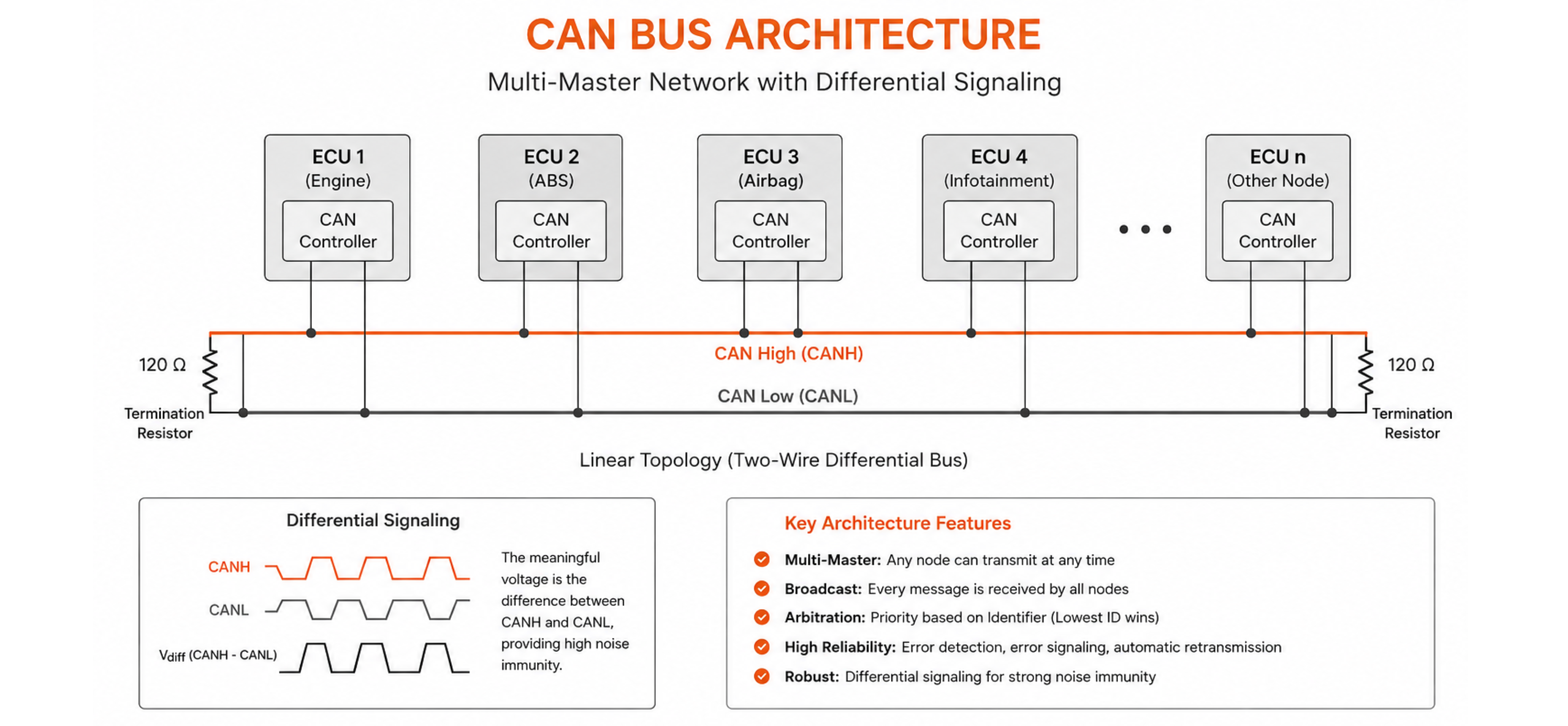
The physical layer of the CAN bus protocol uses two wires: CAN High (CANH) and CAN Low (CANL). These wires carry differential signals, meaning the meaningful voltage is the difference between them rather than the absolute level of either wire. This differential signalling gives the controller area network its strong noise immunity. Nodes connect to the bus in a linear topology, with 120-ohm termination resistors at each end to prevent signal reflections.
The CAN bus protocol is a multi-master network — any node can initiate a transmission at any time. There is no bus master, no token passing, and no central scheduler. Bus access is controlled entirely through CAN bus message arbitration, making the protocol both deterministic and highly fault-tolerant.
The Four CAN Bus Frame Types
Understanding CAN bus frame types is fundamental to working with the protocol. There are four CAN bus frame types, each serving a distinct function:
- Data Frame: The most common of the CAN bus frame types, a Data Frame carries between 0 and 8 bytes of payload data from one node to all others on the bus. It contains an identifier, a Data Length Code (DLC), the actual data bytes, and a cyclic redundancy check (CRC) for error detection.
- Remote Frame: A Remote Frame is used by a node to request that another node transmit a specific Data Frame. It carries the same identifier as the requested Data Frame but contains no payload. Remote Frames are one of the less commonly used CAN bus frame types in modern designs.
- Error Frame: Any node that detects a protocol violation transmits an Error Frame to signal all other nodes that the preceding message was corrupted. This is the CAN bus protocol's primary self-healing mechanism and a key reason the controller area network is trusted in safety-critical applications.
- Overload Frame: An Overload Frame is transmitted by a node that requires additional time to process a received message before the next frame arrives. It is the least common of the four CAN bus frame types and is rarely seen in modern, high-performance implementations.
How CAN Bus Message Arbitration Works
CAN bus message arbitration is the process by which the CAN bus protocol resolves simultaneous transmission attempts without losing data or requiring a bus master. When two or more nodes begin transmitting at the same moment, each node monitors the bus while it transmits. The CAN bus protocol uses a dominant/recessive bit scheme: a dominant bit (logical 0) always overwrites a recessive bit (logical 1) on the bus.
During CAN bus message arbitration, each node compares what it is transmitting with what it reads back from the bus. The moment a node transmitting a recessive bit reads back a dominant bit, it knows a higher-priority message is on the bus. That node immediately stops transmitting and waits. The node with the numerically lowest identifier value wins, because lower identifier bits contain more dominant zeros. This non-destructive CAN bus message arbitration process ensures that the highest-priority message always gets through without corrupting other messages.
| CAN Version | Identifier Length | Max Payload | Max Speed |
|---|---|---|---|
| CAN 2.0A (Standard) | 11 bits | 8 bytes | 1 Mbit/s |
| CAN 2.0B (Extended) | 29 bits | 8 bytes | 1 Mbit/s |
| CAN FD | 11 or 29 bits | 64 bytes | Up to 8 Mbit/s |
CAN Bus Protocol in Automotive and Industrial Applications
Modern vehicles contain between 50 and 150 ECUs, each responsible for a subsystem — engine management, ABS, airbags, infotainment, or climate control. These ECUs communicate over multiple CAN bus protocol networks segmented by speed and criticality. This automotive communication protocol is also the physical foundation for higher-layer standards including J1939 for commercial vehicles, ISO 15765 for OBD-II diagnostics, and CANopen for industrial automation. In industrial environments, the controller area network standard's deterministic latency and multi-master architecture make it ideal for distributed sensor and actuator networks in robots, conveyor systems, and process controllers.
Connect and Monitor Your CAN Network with Precisol Automation
Whether you are designing a new CAN bus protocol network, debugging an existing one, or integrating vehicle CAN data with industrial systems, having the right hardware makes the difference. Precisol Automation's CAN Bus Gateway translates between the CAN bus protocol and modern protocols like Modbus and MQTT, enabling seamless integration between vehicle networks and cloud platforms. For development and diagnostics, the CAN to USB Adapter connects directly to any controller area network for real-time frame capture, filtering, and logging.
Explore how this automotive communication protocol drives real-world ECU validation in our CAN data logger case study, or discover how Precisol tools power professional CAN bus network analysis.
Frequently Asked Questions
What is the maximum speed of the CAN bus protocol?
Classic CAN bus protocol supports a maximum data rate of 1 Mbit/s. The usable speed depends on bus length — a 40-metre bus runs at 1 Mbit/s, while a 1,000-metre bus is limited to approximately 50 kbit/s due to propagation delay constraints.
What are the four CAN bus frame types?
The four CAN bus frame types are: Data Frame (carries payload), Remote Frame (requests data from another node), Error Frame (signals a detected fault), and Overload Frame (requests extra processing time between frames). Data Frames make up the vast majority of traffic in normal operation.
How does CAN bus message arbitration work?
CAN bus message arbitration is a non-destructive, bit-wise process. When multiple nodes transmit simultaneously, each monitors the bus while sending. The node with the lower identifier value wins bus access while the other backs off and retries — no data is lost and no bus master is required.
Is the CAN bus protocol still relevant in modern vehicles?
Yes. The CAN bus protocol remains the dominant automotive communication protocol for body, powertrain, and chassis networks. While newer vehicles also use Ethernet for high-bandwidth applications like cameras and ADAS, the controller area network standard continues to handle the majority of real-time ECU-to-ECU communication.