FlexRay Protocol: High-Speed Deterministic Communication for Automotive Safety Systems
14 October 2026
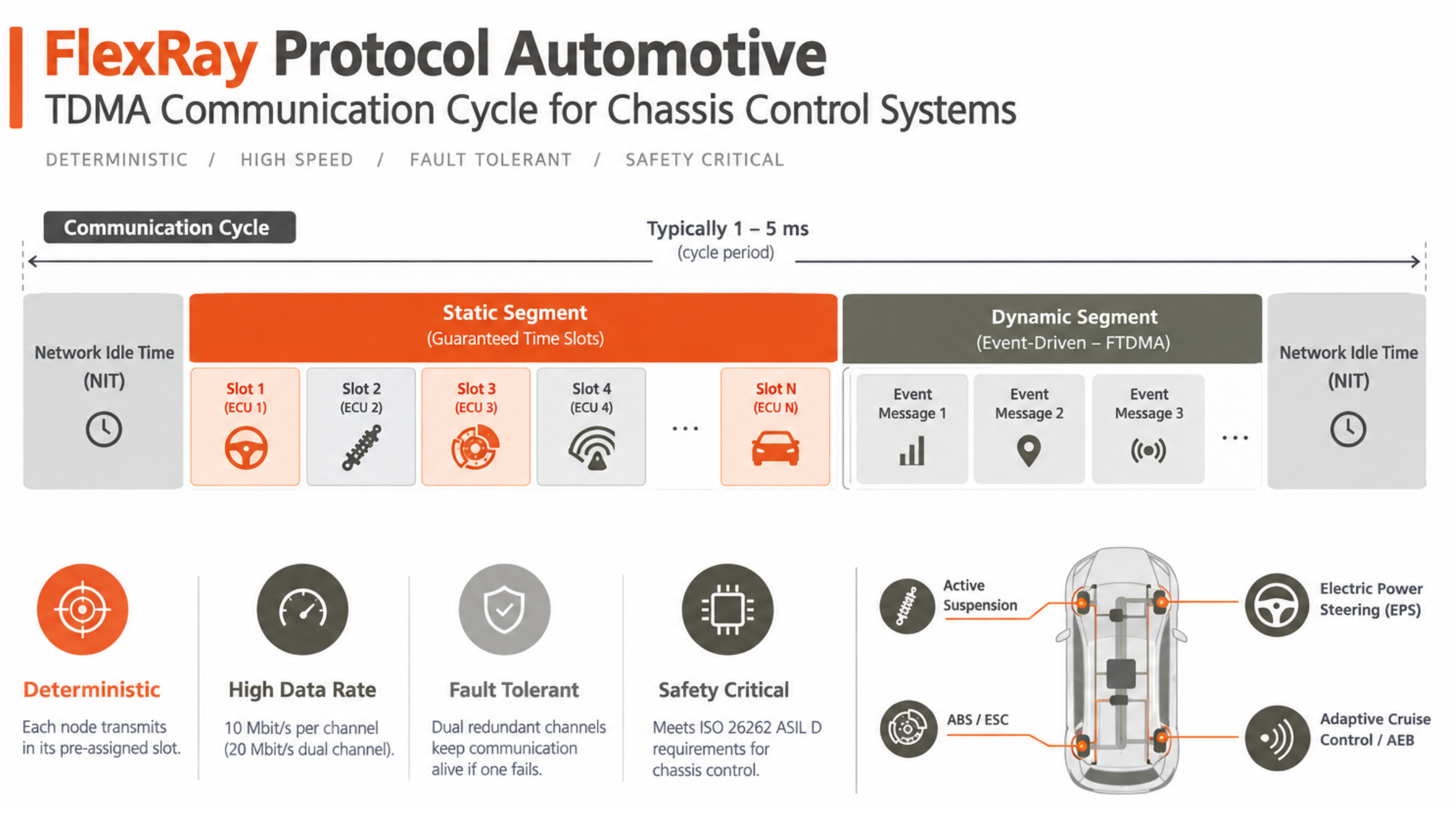
FlexRay protocol automotive was developed to solve the two fundamental limitations of CAN bus that prevent its use in the most demanding automotive safety applications: insufficient data rate and non-deterministic worst-case latency. While CAN bus revolutionised automotive networking from the 1990s and remains the dominant protocol for powertrain, body control, and instrument cluster communication, its CSMA/CD arbitration scheme means that the worst-case delivery time of any message cannot be absolutely guaranteed — under peak bus load, lower-priority messages may be delayed arbitrarily. For most automotive ECUs this is acceptable. For active suspension, steer-by-wire, and brake-by-wire FlexRay chassis control systems, where an actuator response delayed beyond the control loop period can destabilise vehicle dynamics, the non-determinism of CAN bus is unacceptable. FlexRay protocol automotive solves this with FlexRay deterministic communication using TDMA — every node transmits in its pre-assigned slot, every cycle, in the same sequence, guaranteeing that any given message arrives within one cycle period (typically 1–5 ms). At 10 Mbit/s per channel — ten times the rate of classic CAN bus — FlexRay protocol automotive also provides the bandwidth required for the high-frequency sensor data that precision chassis control demands. Understanding the FlexRay vs CAN bus comparison and the FlexRay TDMA protocol architecture is essential for automotive engineers designing or testing safety-critical chassis ECU networks.
FlexRay Protocol Automotive: Architecture and Key Features
- Dual-Channel Fault-Tolerant Topology: FlexRay protocol automotive supports dual-channel operation — two independent physical buses (Channel A and Channel B) connecting all nodes in the network. The dual-channel topology provides redundancy: if one channel develops a fault (short, open, or noise-induced error), communication continues on the remaining channel at full data rate. FlexRay chassis control systems use this redundancy to meet the single-point-of-failure freedom requirements of ISO 26262 ASIL D functional safety. Each channel carries 10 Mbit/s independently; some deployments use both channels simultaneously for 20 Mbit/s aggregate throughput.
- FlexRay TDMA Protocol — Communication Cycle Structure: The FlexRay TDMA protocol organises every communication cycle into a static segment (guaranteed time slots for safety-critical data) and a dynamic segment (FTDMA — event-driven messages in bounded time). The static segment timing is defined at design time in the FlexRay cluster configuration and cannot vary at runtime — this is what makes FlexRay deterministic communication absolute. The network idle time (NIT) segment at the end of each cycle provides the clock synchronisation reference that all nodes use to maintain slot alignment. All FlexRay nodes synchronise to the same global time base using the bus guardian mechanism, guaranteeing that TDMA slot boundaries are observed across the entire FlexRay protocol automotive network.
- FlexRay vs CAN Bus Comparison — When to Choose FlexRay: The FlexRay vs CAN bus comparison for a specific application should start with two questions: Is absolute worst-case latency guarantee required (ASIL D safety function where the control loop period is tighter than CAN bus can guarantee under peak load)? Is 1 Mbit/s or 8 Mbit/s (CAN FD) data rate insufficient? If both answers are yes, FlexRay protocol automotive is justified despite its higher system cost. If only the data rate question applies, CAN FD (8 Mbit/s) may be sufficient. If bandwidth requirements exceed CAN FD, Automotive Ethernet (100BASE-T1 at 100 Mbit/s) is increasingly preferred over FlexRay for non-safety-critical high-bandwidth applications.
- FlexRay Chassis Control Systems — Primary Applications: FlexRay chassis control systems in production vehicles include: active suspension control (requiring sub-millisecond actuator response to wheel speed and acceleration inputs); electric power steering (EPS) with steer-by-wire (direct lateral control — ISO 26262 ASIL D); advanced ABS and ESC systems requiring higher-frequency wheel speed sampling than CAN bus supports; and radar-based active cruise control and emergency brake systems where sensor-to-actuator latency directly affects stopping distance.
FlexRay vs CAN Bus: Technical Comparison
| Feature | CAN Bus (Classic / CAN FD) | FlexRay Protocol Automotive |
|---|---|---|
| Max Data Rate | 1 Mbit/s classic; 8 Mbit/s CAN FD | 10 Mbit/s per channel (20 Mbit/s dual channel) |
| Determinism | Priority-based arbitration — unbounded worst-case for low priority | FlexRay deterministic communication — TDMA guaranteed slot |
| Fault Tolerance | Single bus, bus-level error detection | Dual redundant channels — failure of one channel transparent to application |
| Primary Use | Powertrain, body, instruments — CAN bus ecosystem | FlexRay chassis control systems — ASIL D safety applications |
| Cost/Complexity | Low — CAN transceiver is inexpensive, well-understood | Higher — FlexRay TDMA protocol configuration requires specialised tooling |
FlexRay Protocol Automotive Testing with Precisol Automation
Testing and validating FlexRay protocol automotive networks requires bus analysis tools that decode the TDMA frame structure, verify static slot assignments, and measure timing accuracy across the full operating temperature range. While Precisol Automation's CAN Bus Gateway and CAN Data Logger focus on the CAN bus domain, they are used in the same vehicle test campaigns as FlexRay analyser tools — capturing CAN bus traffic on powertrain and body networks that interact with FlexRay chassis control systems through gateway ECUs.
See CAN bus data acquisition in embedded network testing in our autonomous mobile robot testing case study, or explore AMR field testing with CAN bus gateway for multi-protocol embedded network test methodologies applicable to FlexRay vs CAN bus comparison validation campaigns.
Frequently Asked Questions
What is FlexRay protocol and why was it developed for automotive use?
FlexRay protocol automotive is a 10 Mbit/s deterministic serial communication standard developed for safety-critical chassis control systems where CAN bus's non-deterministic arbitration is insufficient. FlexRay deterministic communication uses TDMA — each node transmits in a pre-assigned time slot, guaranteeing bounded worst-case latency for ISO 26262 ASIL D applications. Dual-channel topology provides fault-tolerant operation for steer-by-wire, active suspension, and advanced brake systems.
What is the difference between FlexRay vs CAN bus for automotive networks?
FlexRay vs CAN bus comparison: CAN bus (1–8 Mbit/s) uses priority arbitration — latency unbounded for low-priority messages under high load; FlexRay protocol automotive (10 Mbit/s/channel) uses FlexRay TDMA protocol — every slot is pre-scheduled, worst-case timing is guaranteed. FlexRay chassis control systems use dual redundant channels for ASIL D safety. CAN bus remains dominant for powertrain and body ECUs; FlexRay is justified only where CAN bus's determinism or bandwidth is genuinely insufficient.
How does FlexRay TDMA protocol work and what is the FlexRay communication cycle?
FlexRay TDMA protocol divides each fixed-length communication cycle into a static segment (guaranteed pre-assigned slots for safety-critical data — FlexRay deterministic communication) and a dynamic segment (FTDMA for event-driven lower-priority messages). All nodes synchronise to the same global clock via the bus guardian — ensuring TDMA slot boundaries are observed across the entire network. Cycle period is 1–5 ms configurable, defining the worst-case delivery guarantee for FlexRay chassis control systems.