XCP Protocol: ECU Calibration and Measurement in Modern Automotive Development
15 October 2026
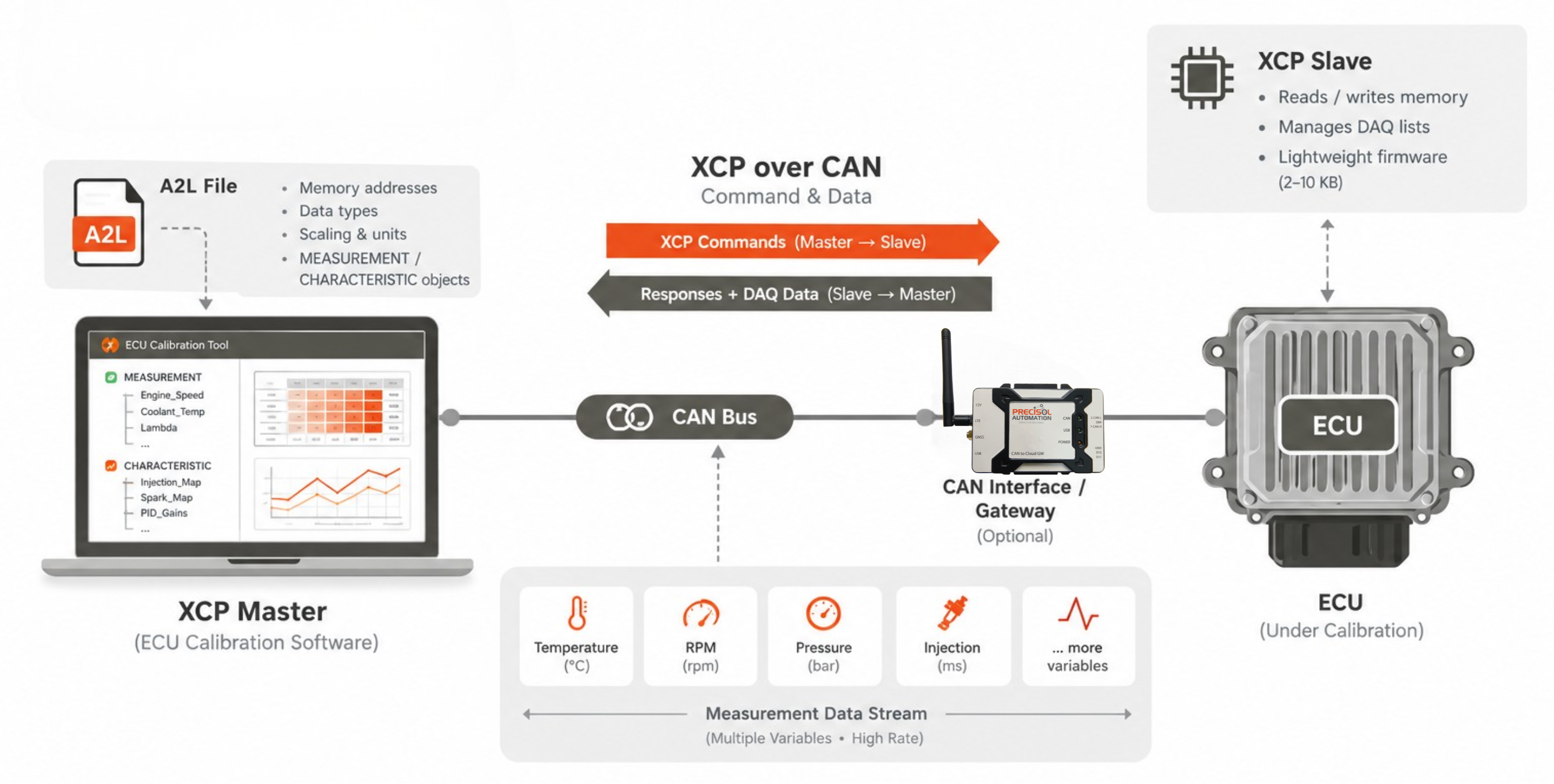
XCP protocol ECU calibration is the universal standard that gives automotive engineers the ability to reach inside a running ECU's microcontroller — reading internal variables in real time and writing calibration parameters live — while the engine is running on a dynamometer or the vehicle is being driven on a test track. Without XCP protocol ECU calibration, engine calibration engineers would have to stop the vehicle, flash modified calibration data to ECU memory, restart the engine, and repeat — a cycle that could take 10–30 minutes per parameter change. With XCP, calibration parameters (injection timing maps, air charge models, PID controller gains) can be modified in milliseconds while the engine runs, and measurement data streams continuously from hundreds of internal ECU variables simultaneously. XCP over CAN measurement — using the vehicle's existing CAN bus network as the physical transport — is the most widely deployed implementation, enabling XCP protocol ECU calibration with a standard CAN hardware interface. Understanding the relationship between the A2L file XCP calibration description and the XCP master tool, the difference between XCP vs OBD diagnostic protocol access modes, and the ECU calibration software tools that implement the XCP master are essential knowledge for anyone working in powertrain calibration, software validation, or automotive test engineering.
XCP Protocol ECU Calibration: How It Works
- XCP Master and Slave Architecture: XCP protocol ECU calibration uses a master-slave model: the ECU under calibration contains an XCP slave — a lightweight firmware module (typically 2–10 KB ROM footprint) that listens for XCP commands on the selected transport (CAN, Ethernet, SPI, USB), executes memory reads and writes, and manages the DAQ (Data Acquisition) lists that stream measurement data back to the master. The XCP master is the ECU calibration software tools running on the calibration engineer's laptop (ETAS INCA, Vector CANape, dSPACE ControlDesk, or open-source tools such as XCPlite) — it sends XCP over CAN measurement commands and receives data.
- A2L File — The ECU Memory Map: The A2L file XCP calibration description (ASAM MCD-2 MC format) is the interface contract between the ECU software and the ECU calibration software tools. Every variable that can be measured or calibrated is listed with its: ECU memory address (absolute or section-relative); data type (uint8, int16, float32, etc.); scaling formula (slope and offset to convert raw ADC counts to engineering units); unit (°C, rpm, ms); and grouping into MEASUREMENT objects (read-only live variables) and CHARACTERISTIC objects (calibratable maps, curves, and scalars). A2L file XCP calibration generation is automated from ECU source code in AUTOSAR workflows and from compiler symbol files in legacy codebases — but for older ECUs without automated generation, the A2L may need to be created manually from the calibration parameter list.
- XCP over CAN Measurement — Transport Details: XCP over CAN measurement uses two CAN IDs — one for XCP command packets (master to slave) and one for XCP response and DAQ data packets (slave to master). The maximum XCP payload per CAN frame is 7 bytes (CAN DLC 8 minus 1 header byte). For high-frequency measurement of many variables, XCP over CAN measurement uses DAQ lists — pre-configured groups of variables read from ECU memory at each configured rate and packed efficiently into CAN frames. XCP over CAN FD (8 Mbit/s, up to 64-byte payload) dramatically increases DAQ throughput. XCP over Ethernet (XCP on UDP/IP at 100 Mbit/s or 1 Gbit/s) is used for Adaptive AUTOSAR ECUs where XCP protocol ECU calibration data volumes exceed what CAN can carry.
- XCP vs OBD Diagnostic Protocol — Key Differences: The XCP vs OBD diagnostic protocol question arises when comparing development tooling to production service tools. XCP protocol ECU calibration provides direct access to any ECU memory location using the A2L file XCP calibration map — intended for authorised development and calibration engineers. OBD-II (J1979) provides access only to standardised PIDs via the SAE J1962 diagnostic connector — intended for emissions inspection and aftermarket service. OBD is always available in production vehicles; XCP is typically only in development firmware builds and disabled in production ECUs. Both can run over CAN, but serve entirely different purposes in the vehicle development lifecycle.
XCP Protocol ECU Calibration: Transport Comparison
| XCP Transport | Bandwidth | ECU Calibration Software Tools Use Case |
|---|---|---|
| XCP over CAN (2.0B) | ~50–100 variables at 10 ms — XCP over CAN measurement | Powertrain and chassis ECUs on existing CAN networks |
| XCP over CAN FD | ~400–800 variables at 10 ms | High-channel-count ADAS ECU calibration on CAN FD networks |
| XCP over Ethernet | Thousands of variables at 1 ms — EV/ADAS high-bandwidth | Adaptive AUTOSAR ECUs, EV battery management, ADAS compute |
| XCP vs OBD — OBD-II (for reference) | ~3–5 PIDs at 100 ms (production diagnostics only) | Service technician emissions and fault code access — not calibration |
XCP Protocol ECU Calibration Support with Precisol Automation
Precisol Automation's CAN Data Logger captures the raw CAN bus traffic that includes XCP over CAN measurement packets — enabling engineers to record complete calibration sessions alongside the production CAN network traffic for post-process correlation and validation. The CAN Bus Gateway bridges between CAN bus networks and enables calibration session routing across network segments during XCP protocol ECU calibration on complex multi-network test vehicles.
See CAN bus data capture during vehicle test campaigns in our autonomous mobile robot testing case study, or explore AMR field testing with CAN bus gateway for multi-ECU CAN network logging approaches applicable to ECU calibration software tools integration and A2L file XCP calibration session recording.
Frequently Asked Questions
What is XCP protocol and how does ECU calibration work?
XCP protocol ECU calibration (ASAM AE MCD-1 XCP) enables calibration tools to read and write ECU microcontroller memory variables in real time during vehicle operation — without stopping or reflashing. The ECU runs an XCP slave firmware module; the ECU calibration software tools (INCA, CANape) act as XCP master via XCP over CAN measurement. The A2L file XCP calibration description maps variable names to memory addresses, enabling live parameter changes (injection timing maps, PID gains) and continuous measurement data streaming during drive cycles.
What is the difference between XCP vs OBD for ECU diagnostics?
XCP vs OBD diagnostic protocol: XCP protocol ECU calibration gives authorised development engineers direct access to any ECU memory variable using the A2L file XCP calibration map — intended for calibration, measurement, and validation during development. OBD-II provides standardised access to fixed PIDs (engine speed, temperature, fault codes) for service technicians and emissions inspection — always available in production vehicles. XCP is typically only in development firmware builds; OBD is always in production ECUs.
What is an A2L file in XCP calibration and how is it used?
An A2L file XCP calibration description (ASAM MCD-2 MC format) maps every measurable and calibratable ECU variable to its memory address, data type, scaling, and unit. Without the A2L file, ECU calibration software tools cannot interpret raw bytes from ECU memory. A2L files are generated automatically from AUTOSAR builds or compiler symbol tables, loaded into the XCP master tool, and used throughout XCP over CAN measurement sessions. They contain IP-sensitive memory layout information and are typically distributed only to authorised development teams.