RS485 Network Wiring: Best Practices for Noise-Free Industrial Deployments
08 July 2026
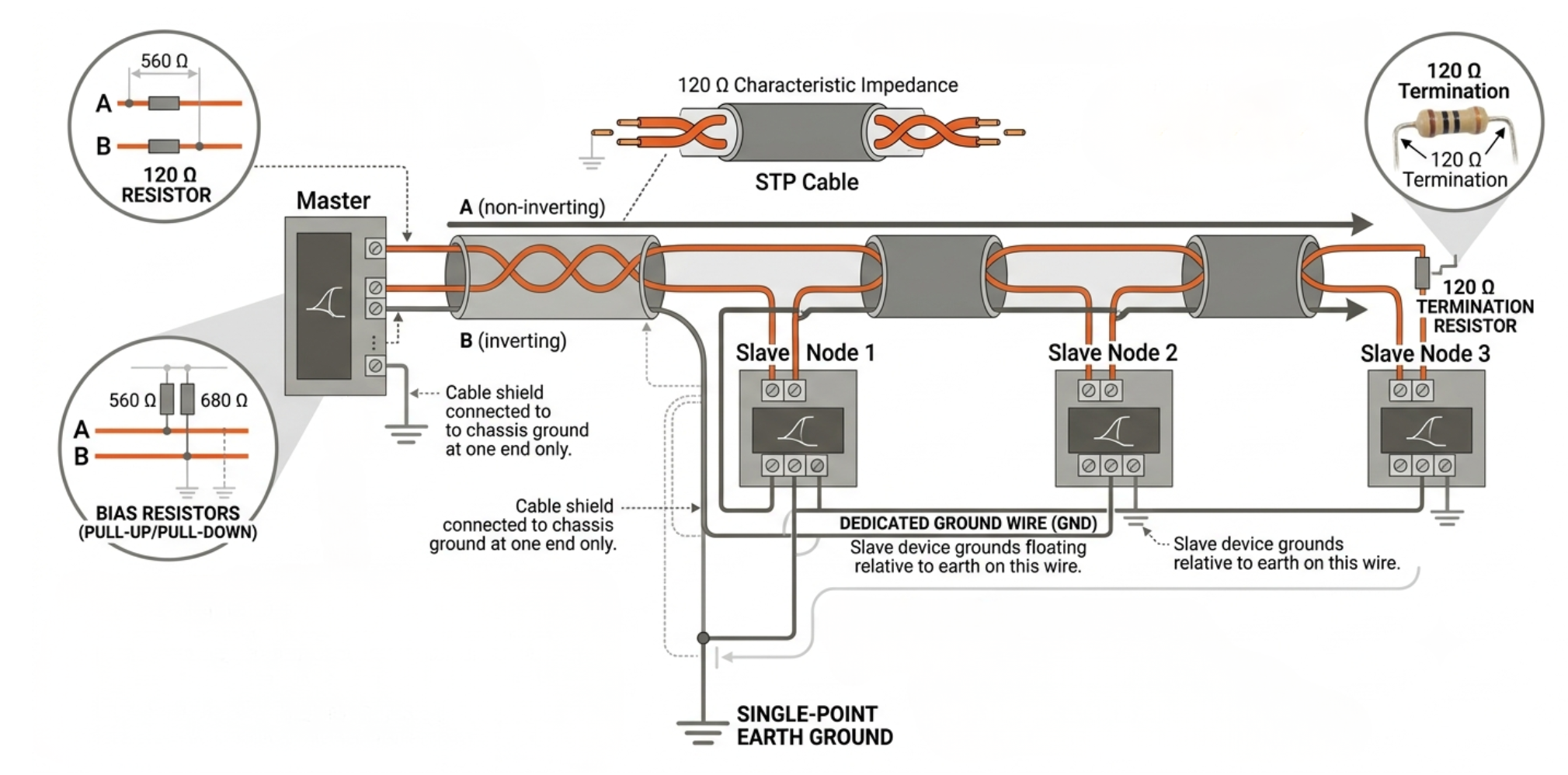
Getting RS485 network wiring right is the difference between a rock-solid industrial communication backbone and an intermittent nightmare that fails unpredictably. RS485 is designed to be noise-immune — but only when the RS485 network wiring follows established best practices for RS485 bus termination, RS485 cable length management, cable routing to minimise industrial wiring noise, and correct RS485 grounding. Ignoring any one of these factors can turn a robust differential serial protocol into a source of random communication errors that are frustratingly difficult to diagnose.
Cable Selection: The Foundation of RS485 Network Wiring
The foundation of reliable RS485 network wiring is the cable itself. Always use shielded twisted-pair (STP) cable with a characteristic impedance of 100–120 ohms. The twist in twisted-pair cable is what gives RS485 its differential noise immunity — the two conductors are exposed to the same electromagnetic fields, so the differential signal is preserved while common-mode industrial wiring noise is cancelled at the receiver. A typical specification for RS485 network wiring cable is 22 AWG STP with 120 ohm impedance, such as Belden 9842 or equivalent. Never use untwisted cable or split wires from a multi-conductor cable for RS485 network wiring — the loss of twist cancellation destroys the differential noise rejection that makes RS485 valuable in industrial environments.
Route RS485 network wiring away from power cables, VFD output wiring, and transformer inductors — the primary sources of industrial wiring noise in plant environments. Where cable crossings are unavoidable, cross RS485 wiring at 90 degrees to power conductors to minimise capacitive coupling.
RS485 Bus Termination: The Most Commonly Missed Step
Correct RS485 bus termination is critical at baud rates above 19,200 baud. Without proper RS485 bus termination, signal reflections from the end of the bus travel back along the wire and corrupt the received waveform. The principle: RS485 bus termination resistors with a value matching the cable's characteristic impedance (typically 120 ohms) must be placed at both physical ends of the bus — not at intermediate nodes and not at the master only.
- Where to place RS485 bus termination: At the two devices located at the physical ends of the bus daisy chain. The RS485 bus termination resistor connects between the A and B conductors at each end.
- What not to do with RS485 bus termination: Never install RS485 bus termination at intermediate nodes. Never use a different resistor value — 120 ohms is specified because it matches standard twisted-pair cable impedance. Never install RS485 bus termination at only one end.
- Low-speed exception: At baud rates below 19,200 baud and on short RS485 cable lengths under 100 metres, RS485 bus termination can often be omitted without communication errors — but always include it for reliable long-term operation.
RS485 Cable Length vs Baud Rate
RS485 cable length and baud rate have an inverse relationship driven by the propagation delay of the signal and the rise time requirements. The rule of thumb: maximum RS485 cable length in metres equals 10^8 divided by the baud rate. In practice:
| Baud Rate | Maximum RS485 Cable Length | Typical Application |
|---|---|---|
| 9,600 baud | 1,200 m | Long-distance Modbus RTU |
| 115,200 baud | ~800 m | Standard industrial RS485 network wiring |
| 500 kbit/s | ~200 m | High-speed Modbus / Profibus |
| 1 Mbit/s | ~100 m | High-speed RS485 short-run networks |
For RS485 cable length runs that exceed these limits, install RS485 repeaters to regenerate the signal. A repeater splits the bus into two segments, each with its own RS485 bus termination — effectively doubling the achievable RS485 cable length while maintaining signal integrity.
RS485 Grounding: The Overlooked Essential
RS485 grounding is frequently omitted because engineers assume differential signalling eliminates all ground concerns. This is incorrect. RS485 transceivers specify a common-mode input voltage range — typically -7V to +12V. If the ground potential difference between two devices on the RS485 network wiring exceeds this range, the transceivers can be damaged or produce constant communication errors despite the twisted-pair wiring. RS485 grounding via a third conductor — a dedicated ground wire connecting the ground terminals of all devices on the bus — keeps the common-mode voltage within specification and prevents this class of industrial wiring noise failure. The RS485 grounding conductor should be connected to earth at only one point to avoid ground loop currents; connect it to the master device ground and leave all slave device grounds floating on the RS485 grounding wire.
Bias Resistors: Ensuring Defined Idle State
When no RS485 device is transmitting, the bus is in an idle (high-impedance) state. Without pull-up and pull-down bias resistors, industrial wiring noise can drive the idle bus to an undefined voltage — causing false start bits and communication errors. Bias resistors (typically 560 ohm to 1 kohm) pull the A line high and the B line low during idle, ensuring the bus holds a defined recessive state between transmissions. Most RS485 network wiring best practices recommend placing bias resistors at the master node only.
Deploy Reliable RS485 IIoT Connectivity with Precisol Automation
Even perfectly wired RS485 network wiring needs an intelligent gateway to bring its data into modern IIoT platforms. Precisol Automation's RS485 Serial IIoT Edge Gateway terminates your RS485 bus with correct built-in RS485 bus termination options, handles Modbus RTU polling, and publishes data to cloud platforms via MQTT — eliminating the need for a separate PC or SCADA server. For distributed RS485 IO expansion, the Serial RS485 IO Controller provides robust multi-node connectivity on the RS485 multi-drop bus.
See reliable RS485 network wiring with proper RS485 bus termination and RS485 grounding in a real industrial deployment in our pump health monitoring case study, or explore how Precisol enables remote digital I/O monitoring over RS485.
Frequently Asked Questions
What termination resistor value should I use for RS485 bus termination?
Use 120-ohm resistors for RS485 bus termination — placed at both physical ends of the bus. This matches standard twisted-pair cable impedance. Incorrect RS485 bus termination is the most common cause of signal reflection errors in RS485 network wiring at baud rates above 19,200.
What is the maximum RS485 cable length?
RS485 cable length depends on baud rate: 1,200 m at 9,600 baud, ~800 m at 115,200 baud, ~100 m at 1 Mbit/s. Always use shielded twisted-pair cable for long RS485 cable length runs to minimise industrial wiring noise. RS485 repeaters can extend the bus beyond these limits.
Why does RS485 grounding matter for industrial wiring noise?
RS485 grounding keeps common-mode voltage within the transceiver's specified range. Without RS485 grounding, ground potential differences between devices can exceed -7V to +12V, causing receiver errors or transceiver damage — even with perfect RS485 network wiring differential signalling and RS485 bus termination in place.